A power inverter circuit is a circuit that converts DC power to AC power. You can make the AC power be any level that you want and to any frequency that you want. The popular values to boost the AC voltage level to is either 110-120V or 220-140V because these are the AC voltages that are used worldwide.
We use either 120/ 240V, with 120V being much more common. Therefore, for this circuit, we will have an output AC voltage of 120V. We accomplish this voltage, we use a transformer with a 1:10 amplification. So in order to do this circuit, we will need a 120VAC power supply transformer that takes an input of 12V. How we accomplish the frequency of the circuit is through a resistor-capacitor (RC) network. The standard frequency is 60Hz for AC voltage from wall outlets. Later on, we can test the frequency with either a multimeter, oscilloscope, or frequency counter to ensure its accuracy. Worldwide, frequencies are either 50Hz or 60Hz, so there is not much variation. So with a slight tweak of values, we can have either frequency. By doing this circuit and getting the AC voltage amplitude and frequency that our country we live in uses, we are imitating the function of an AC wall outlet. Therefore, devices that are powered by connecting to a wall outlet can now be powered directly by our inverter circuit.
If you’re dealing with a 1000W pure sine wave power inverter, and the device you’re power needs 1500W such as a typical heater running in high power, the inverter circuit won’t be able to do it. This is why if you look at commercial inverters, they will have specifications to the amount of power they can output. Power is a function of voltage vs current. So if the inverter puts out 120 volts and can output up to 12A of current, it has a power rating of 1440 watt.
We’ll show in detail how to build this circuit below.
Components Needed
- 12V Battery
- Power Transformer 120VAC Primary 12VAC Secondary
- 2 2N2222 BJT transistors
- 2 IRF640 Power MOSFETs
- 2 16.5KΩ resistors
- 2 680Ω resistors
- 2 1µF capacitor
The type of battery we will use for this circuit is one of those big 12V batteries, such one you would find in a car. These types of batteries give out 12V with several amperes of current output capability, typically about 7A of current. This allows for large output powering. This is not a small battery such as a ‘AA’ battery.
A power inverter is really a powerful backup power supply used frequently in the event of AC mains power goes down. Therefore, it uses heavy duty backup power.
In case you just want to test the circuit without actually connecting all the true components, you can use a DC power supply switched to 12V with current capability turned on to replicate the effect of a 12V battery.
Apart from the battery, we need a power transformer. Since we are using a 12V battery to supply our voltage, we need a power transformer that converts from 12VAC to 120VAC. But you don’t have to choose this voltage. You may want another voltage. In that case, just make sure it can use the 12VAC to convert it into the voltage you want, whether that’s 110VAC or 220VAC or 230VAC or 240VAC. This may be the voltage that your device operates on. For this circuit, you can use any output AC voltage, without it affecting any other part of the circuit. Then we just need a few transistors, and resistors and capacitors.
Power Inverter Circuit
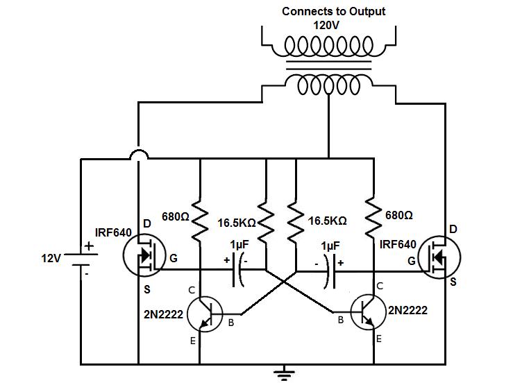
The power inverter circuit that we will build with a power transformer along with a few simple components is shown below.
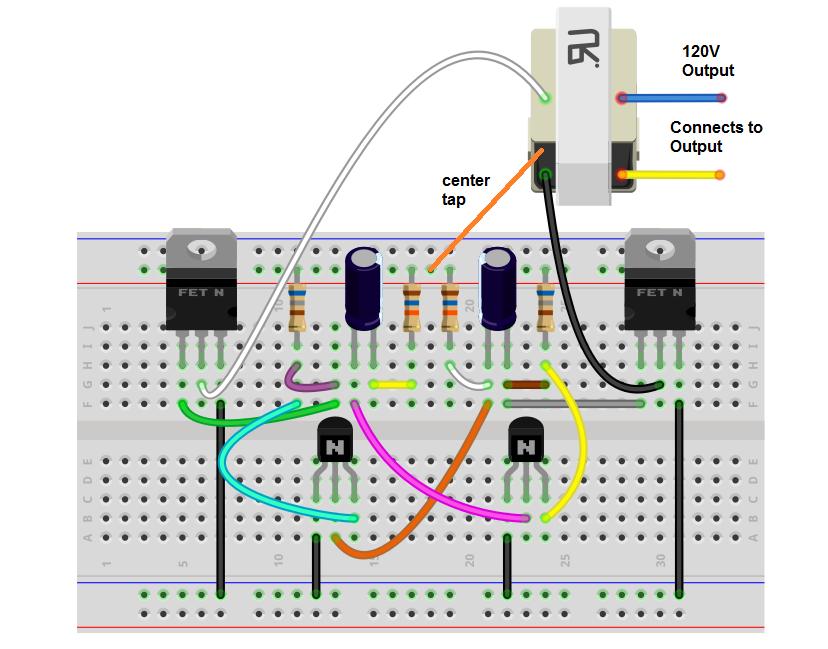
The breadboard circuit of the circuit above is shown below.
- Step 1: You can use a variety of voltages to power the circuit. If you have a transformer with a 1:10 turns ratio and you want 120V, then 12V is what you should use, since 12V*10= 120V. If you are using a transformer with a 1:20 ratio and 120V as output, then 6V is the voltage to use.
- Step 2: Now the circuit composed of the 2 2N2222 NPN transistors, the 2 1µF electrolytic capacitors, the 2 680Ω resistors, and the 16.5KΩ resistors form a multivibrator circuit that determines the frequency of the output. It’s really the 1µF capacitors and the 16.5KΩ resistors that chiefly determine the frequency. Since the resistor and capacitor pair form an RC network, the time constant that the output switches on and off at is determined by the formula, =RC= (16.5KΩ)(1µF)= 0.0165s. The inverse of the time constant is the frequency, f=1/τ= 1/0.0165s ≈ 60Hz.
- Step 3: This part of the circuit is a multivibrator. It creates a closely resembling sinusoidal waveform. When one transistor is on, the other is off.
- Step 4: So now we’re at the last part of this circuit – connecting it to the transformer. So the transformer is a device made up of 2 coils. There is a primary coil and a secondary coil. We connect the output of this circuit to the primary coil. This induces a voltage in the secondary in proportion to the turns ratio of the transformer.
It may be difficult to find a step up transformer that has a 1:10 turns ratio. So a step-down transformer can be used in place. With a step-down transformer, however, instead of connecting the multivibrator circuit to the primary coil, we connect it to the secondary coil. Then we connect the output of the transformer to the primary coil. This is if we cannot find a step-up transformer. Just make sure not to exceed the limits of the primary and secondary coils. For example, if using a 120V primary coil and a 24V secondary coil, do not exceed the 24V on the secondary coil. This is the maximum rating, so it should not be exceeded.
If you want to be able to power on and off the inverter without having to disconnect the battery or DC power supply, a switch can be added right above the positive voltage of the DC power source. So if you want to turn off the inverter without having to disconnect the battery every time, you simply open the switch, allowing no power to the circuit.