An inverter is an equipment which will convert a battery voltage or any DC (normally a high current) into a higher mains equivalent voltage (120V or 220V), however unlike an UPS inverters may lack one feature, that’s these may not be able to switch from mains battery charging mode to inverter mode and vice versa during grid power failure and restoration situations.
Converting an Inverter to UPS
A power inverter can be easily converted to an UPS with a few simple modifications or rather additions with their existing circuitry.
The lacking or missing change over feature in an inverter can be upgraded by including a few number of relay stages within its circuit, as explained in the following sections:
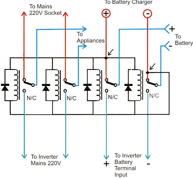
Referring to the figure below, we see that the above requirement is implemented by using 4 SPDT relays whose coils are wired up in parallel and joined with a mains operated DC source, which could very well be the battery charger DC output. It means during the presence of mains input the relays would be energized such that their N/O contacts get connected with the individual relay poles and the respective electrical gadgets which could be seen connected with the poles..
The left two relays can be seen with their N/ O contacts connected with the mains AC input, while the N/ Cs are terminated with the inverter mains output. The relays at the right side have their N/O contacts rigged with battery charger (+)/ (-) inputs, and the N/ Cs are integrated to the inverter DC input.
The above data ensures the following actions during mains presence and failure situations:
When mains AC is present, the appliances get connected to the available mains power via the left pair of relay poles, while the battery is able to get the required charging voltage through the right hand relay poles. This also ensures that the inverter is cut-off via the N/C points from the battery and is no longer able to operate.
In a situation when mains AC fails, the relay contacts revert to their N/C contacts, giving rise to the following actions:
The battery instantly gets connected with the inverter DC input via the right hand side relay N/C contacts, such that the inverter becomes operative and its output starts producing the required mains back up voltage.
At the same instant the above inverter mains voltage now gets switched to the appliances via the left hand side relay N/C contacts ensuring that the appliances do not experience an interruption while the positions revert in the course of the above actions.
Selecting the Relays
The relays must selected with low coil resistance type so that they operate under higher switching currents, and therefore are able to “hammer” the contacts much harder and quicker compared to the lower resistance coil relays. This will ensure the changeover time to be rapid within milliseconds which happens to be the most crucial factor with UPSs and inverters needing to be converted into UPS systems.
In the above diagram if an automatic battery charger is used, the supply would be cut off once the battery is fully charged, which would also cut off the supply to the relays forcing the inverter to switch ON even while the mains is present.
To avoid this issue, the relays must be powered through a separate power supply as shown in the following diagram. A capacitive type of power supply circuit could be seen here, which makes the design much compact.
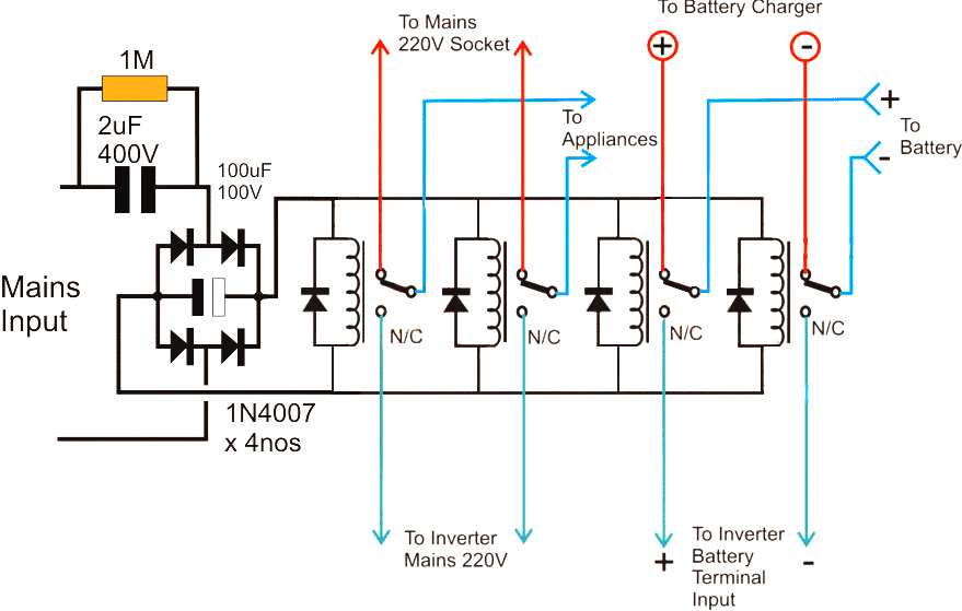
Note: Please connect a 1K resistor across the filter capacitor associated with the bridge rectifier, this is to ensure its quick discharging during a mains failure, and an instant switching of the relevant relays.