Today, we will explain a few circuit concepts which can be employed for converting or modifying any ordinary square wave inverter to a sophisticated sine wave inverter design. Before studying the various designs explained in this article, it would be interesting to know the factors which typically makes a sine wave inverter more desirable than a square wave design.
How Frequency Works in Inverters?
Power inverters basically involve frequency or oscillations for implementing the boost and inversion actions. The frequency as we know is generation of pulses at some uniform and calculated pattern, for example a typical inverter frequency may be rated at 50Hz or 50 positive pulses per second.
The fundamental frequency waveform of an inverter is in the form of square wave pulses. As we all know a square wave is never suitable for operating sophisticated electronic equipment such as TV, music players, computers etc.
The AC (alternating current) mains that we acquire at our domestic mains outlet also consists of pulsating current frequency, but these are in the form of sinusoidal waves or sine waves. It’s normally at 50Hz or 60Hz depending upon the particular country utility specs. The above mentioned sine curve of our home AC waveform refers to the exponentially rising voltage peaks which constitute the 50 cycles of the frequency.
Since our domestic AC is generated through magnetic turbines, the wave form is inherently a sine wave, so doesn’t require any processing further and becomes directly usable in homes for all types of appliances. Conversely in inverters, the fundamental waveform are in the shape of square waves which needs thorough processing in order to make the unit compatible with all types of equipment.
Difference between Square Wave and Sine Wave Inverter
What’s the differences between sqare wave and sine wave inverter? As shown in the figure, a square wave and sine wave may have identical peak voltage levels but the RMS value or the root mean square value may not be identical. This aspect is what that makes a square wave particularly different from a sine wave even though the peak value may be the same.
Therefore a square wave inverter working with 12V DC would generate an output equivalent to say 330V just like a sine wave inverter operating with the same battery but if you measure the output RMS of both the inverters, it would differ significantly (330V and 220V).
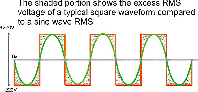
The image incorrectly shows 220V as the peak, actually it should be 330V.
In the above diagram, the green colored waveform is the sine waveform, while the orange depicts the square waveform. The shaded portion is the excess RMS which needs to be leveled of in order to make both the RMS values as close as possible.
Converting a square wave inverter into a sine wave equivalent thus basically means allowing the square wave inverer to produce the required peak value of say 330V yet having an RMS just about equal to its sine wave counterpart.
How to Convert/ Modify a Square Waveform to Sine Waveform Equivalent?
This can be done either by carving a square wave sample into a sine wave form, or simply by chopping a sample square waveform into well calculated smaller pieces such that its RMS becomes very close to a standard mains AC RMS value.
For carving a square wave to a perfect sine wave, we can employ a wien bridge oscillator or more precisely a “bubba oscillator” and feed it to a sine wave processor stage. This method would be too complex and is therefore not a recommended idea for implementing an existing square wave inverter to a sine wave inverter.
The more feasible idea would be to chop the associated square wave at the base of the output devices to the required RMS degree.
Here the lower AMV generate pulses at high frequency whose mark/ space ratio can be suitably altered with the help of preset VR1. This PWM controlled output is applied to the gates of the mosfets in order to tailor their conduction into the stipulated RMS value.
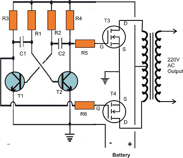
The first diagram shows an square wave inverter circuit. By adding a simple AMV chopper we can break down the pulses at the base of the relevant mosfets to the required degree.
Modified square wave to sine wave equivalent inverter version of the above circuit.