The success of a DC to AC power inverter installation depends mainly on the methods and materials used for the installation. Low DC input voltage inverters (12 or 24 Volts DC) require high DC input currents. This article will guide you through a successful power inverter installation.
Using the existing alternator and battery, what are the system limits for a practical inverter installation using the existing under-the-hood alternator and battery? A majority of utility vehicles have a 100 to 130A alternator together with one or two group-27 batteries. Although the alternator cannot keep up with a continuous full-load current demand of more than 50A, it can provide enough for short term power use. In many cases the use of electrical power to do work is intermittent (using tools off and on for short periods of time). In these cases the alternator is able to “keep up” with power use and recharge the battery. There have been many successful installations of a 2000 watt inverter in such trucks.
Other successful, smaller installations consist of an 1100W inverter system in a smaller utility van or truck:
- Alternator rated at least 85 Amperes.
- A deep-cycle battery, group 27 or larger in size.
- Wire from the inverter to the battery is 2 gauge at up to 15 feet (one way distance)
Mounting the Inverter
Bolt the inverter securely on either a platform or bulkhead. Leave at least one inch of space all around the cabinet and especially above the cabinet for warm air to move out. The inverter face and the side where large DC cables enter should be visible and accessible for ease of wiring, ground fault interrupter testing and status lights viewing.
Fuse Holder Installation
All wiring from a battery must be protected with the proper size fuses. All fuses and fuse holders should be located within 18 inches of the battery. Additional fuse holders may be required if the inverter is connected to the engine battery instead of the alternator, or if the under-the-hood wiring is upgraded. The auxiliary battery fuse protects the wires to the inverter and the wires to the alternator. Another fuse holder must be mounted at the engine battery if a direct connection is made. These auxiliary battery fuse holders must not be installed in an airtight battery compartment because of the explosion hazard mentioned earlier. Mount the fuse holders in a convenient place within 18 inches of the battery and label the fuse rating adjacent to its holder. Do not place the fuses into the fuse holders until all wiring has been completed.
Battery Installation Compartment
The battery area must be vapor-tight to the interior of the vehicle and vented directly to the exterior. It must be assumed that hydrogen gas is continuously evolving from the battery. This gas is lighter than air and will quickly escape through openings at the top of the compartment. Openings at the bottom of the compartment will let in replacement fresh air. Install several vent-plugs within one inch of both top and bottom of this area. Note that the battery cannot share an airtight area containing spark-producing equipment, such as the inverter or fuses which could ignite the hydrogen gas.
Mounting The Battery
Mount the Battery using hold-downs, trays, or boxes. Secure to a level, clean surface. Battery boxes must be of the vented type to allow for the escape of gases. Allow space around the battery and especially above the battery for ventilation, inspection, and maintenance. The battery should not move more than 1 inch in any direction, even if upside-down. A framework of angle iron, together with a protective cover, can be fabricated for large systems.
DC Wiring
Cabling diagrams
Figures below are diagrams for a smaller power inverter (1000 Watt or less) where no auxiliary battery is being installed.

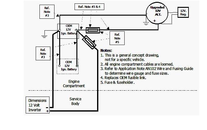
Figure below is a diagram for a larger inverter (1000W or more) where one or more auxiliary batteries are being installed.
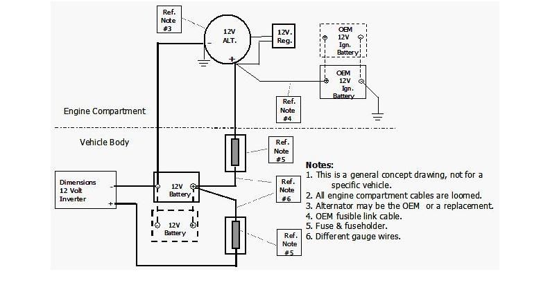
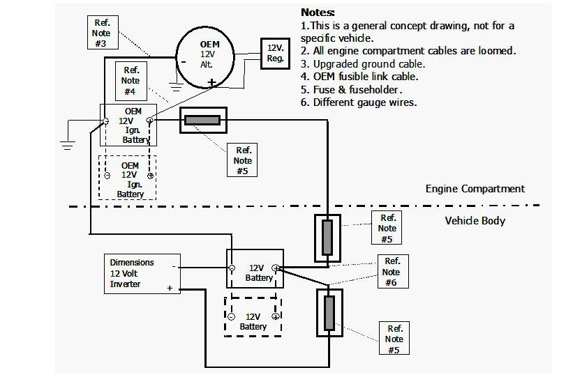
Figure below is a diagram for a larger inverter where one or more auxiliary batteries are being installed and cabling is to the OEM battery.
Routing the cables
- Do not use the vehicle chassis as a conductor.
- When going through a partition, use a protective rubber grommet to prevent abrasion of the insulation. Seal the excess opening with caulk to prevent fume entry.
- When routing under the vehicle, secure the cables with clamps every 18 inches, to prevent a snag. Keep the cables away from the drive shaft, exhaust system, and fuel line.
- When routing in the engine compartment, use high temperature (300°C) loom and route the coolest way possible.