The inverter is used to convert DC to variable AC. This variation can be in the magnitude of voltage, number of phases, frequency or phase difference. According to the type of load of an inverter, there can be two different types of inverters.
- Single-phase Inverter
- Three-phase Inverter
Single-phase Inverter
Generally, residential and commercial load uses single phase power. The single-phase inverter is used for this type of application. The single-phase inverter is further divided into two parts:
- Single Phase Half-bridge Inverter
- Single Phase Full-bridge Inverter
Single phase half bridge inverter
This type of power inverter consists of two thyristors and two diodes and connection is as shown in below figure.
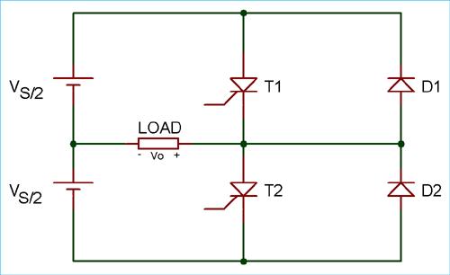
In this case, total DC voltage is Vs and divided into two equal parts Vs/2. Time for one cycle is T sec.
For half cycle of 0< t< T/2, thyristor T1 conducts. The load voltage is Vs/2 due to the upper voltage source Vs/ 2.
For the second half cycle of T/ 2< t< T, thyristor T1 is commutated and T2 conducts. During this period, the load voltage is -Vs/2 due to the lower source Vs/ 2.
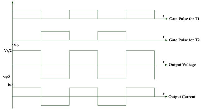
By this operation, we can get alternating voltage waveform with 1/T Hz frequency and Vs/2 peak amplitude. The output waveform is a square wave. It will be passed through the filter and remove unwanted harmonics which give us pure sine waveform. The frequency of the waveform can be controled by the ON time (Ton) and OFF time (Toff) of the thyristor.
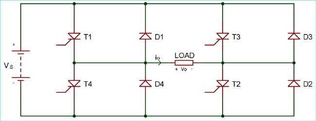
Single phase full-bridge inverter
In this type of inverter, four thyristors and four diodes are used. The circuit diagram of single-phase full bridge is as shown in below figure.
At a time two thyristors T1 and T2 conduct for first half cycle 0< t< T/2. During this period, the load voltage is Vs which is similar to the DC supply voltage.
For second half cycle T/2< t< T, two thyristors T3 and T4 conducts. The load voltage during this period is -Vs.
At a time two thyristors T1 and T2 conduct for first half cycle 0< t< T/2. During this period, the load voltage is Vs which is similar to the DC supply voltage.
For second half cycle T/2< t< T, two thyristors T3 and T4 conducts. The load voltage during this period is -Vs.
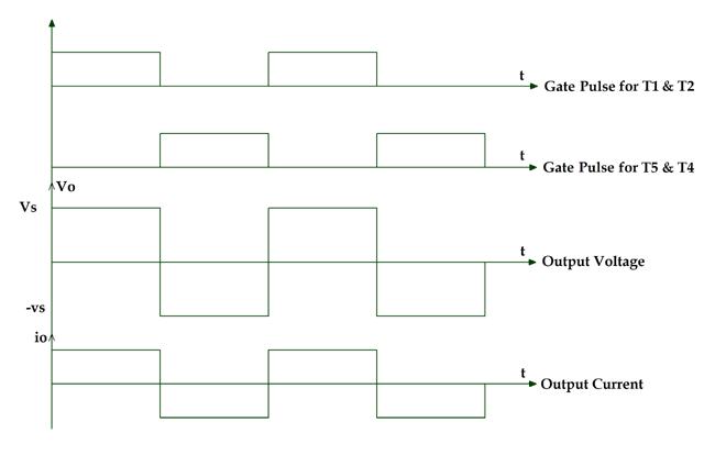
Here we can get AC output voltage same as DC supply voltage and the source utilization factor is 100%. The output voltage waveform is square waveform and the filters are used to convert it into a sine wave.
Three Phase Inverter
In case of industrial load, three phase ac supply is used and for this, we have to use a three-phase inverter. In this type of inverter, six thyristors and six diodes are used and they are connected as shown in below figure.

It can operate in two modes according to the degree of gate pulses.
- 180-degree mode
- 120-degree mode
180-degree mode
In this mode of operation, conduction time for thyristor is 180 degree. At any time of period, three thyristors (one thyristor from each phase) are in conduction mode. The shape of phase voltage is three stepped waveforms and shape of line voltage is a quasi-square wave as shown in the figure.
In this operation, the time gap between the commutation of outgoing thyristor and conduction of incoming thyristor is zero. So the simultaneous conduction of incoming and outgoing thyristor is possible. It results in a short circuit of the source. To avoid this difficulty, 120-degree mode of operation is used.
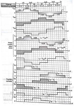
120-degree mode
In this operation, at a time only two thyristors conduct. One of the phases of the thyristor is neither connected to the positive terminal nor connected to the negative terminal. The conduction time for each thyristor is 120 degree. The shape of line voltage is three stepped waveform and shape of the phase voltage is a quasi-square waveform.

The waveform of line voltage, phase voltage and gate pulse of the thyristor is as shown in the above figure.
In any power electronic switches, there are two types of losses; conduction loss and switching loss. The conduction loss means ON state loss in the switch and the switching loss means OFF state loss in switch. Generally, the conduction loss is greater than the switching loss in most of the operation.
If we consider 180-degree mode for one 60-degree operation, three switches are open and three switches are closed. Means total loss is equal to three times of conduction loss plus three times of switching loss.
Total loss in 180-degree = 3 (conductance loss) + 3 (switching loss)
If we consider 120-degree mode for one 60-degree operation, two switches are open and rest of the four switches are closed. Means total loss is equal to two times of conductance loss plus four times of switching loss.
Total loss in 120-degree = 2 (conductance loss) + 4 (switching loss)