An inverter converts the DC electricity from sources such as batteries or fuel cells to AC electricity. The electricity can be at any required voltage; in particular it can operate AC equipment designed for mains operation, or rectified to produce DC at any desired voltage. According to the type of control technique an inverter, there can be four different types of inverters.
- Single Pulse Width modulation (single PWM)
- Multiple Pulse Width Modulation (MPWM)
- Sinusoidal Pulse Width Modulation (SPWM)
- Modified Sinusoidal Pulse Width Modulation (MSPWM)
The output of the power inverter is square wave signal and this signal is not used for the load. Pulse width modulation (PWM) technique is used to control AC output voltage. This control is obtained by the controlling of ON and OFF period of switches. In PWM technique two signals are used; one is reference signal and second is triangular carrier signal. The gate pulse for switches is generated by comparing these two signals. There are different types of PWM techniques.
Single Pulse Width modulation (single PWM)
For every half cycle, the only pulse is available in this control technique. The reference signal is square wave signal and the carrier signal is triangular wave signal. The gate pulse for the switches is generated by comparing the reference signal and carrier signal. The frequency of output voltage is controlled by the frequency of the reference signal. The amplitude of the reference signal is Ar and the amplitude of the carrier signal is Ac, then the modulation index can be defined as Ar/Ac. The main drawback of this technique is high harmonic content.

Multiple Pulse Width Modulation (MPWM)
The drawback of single pulse width modulation technique is solved by multiple PWM. In this technique, instead of one pulse, several pulses are used in each half cycle of the output voltage. The gate is generated by comparing the reference signal and carrier signal. The output frequency is controlled by controlling the frequency of the carrier signal. The modulation index is used to control the output voltage.
The number of pulses per half cycle = fc/ (2*f0)
Where fc = frequency of carrier signal
f0 = frequency of output signal

Sinusoidal Pulse Width Modulation (SPWM)
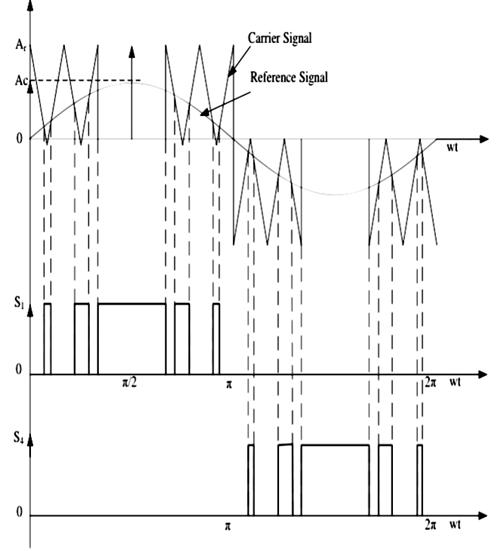
This control technique is widely used in industrial applications. In above both methods, the reference signal is a square wave signal. But in this method, the reference signal is a sine wave signal. The gate pulse for the switches is generated by comparing the sine wave reference signal with the triangular carrier wave. The width of each pulse varies with variation of amplitude of the sine wave. The frequency of output waveform is the same as the frequency of the reference signal. The output voltage is a sine wave and the RMS voltage can be controlled by modulation index. Waveforms are as shown in below figure.

Modified Sinusoidal Pulse Width Modulation (MSPWM)
Due to the characteristic of sine wave, the pulse width of the wave cannot be changed with variation in the modulation index in SPWM technique. That is the reason, MSPWN technique is introduced. In this technique, the carrier signal is applied during the first and last 60-degree interval of each half cycle. In this way, its harmonic characteristic is improved. The main advantage of this technique is increased fundamental component, reduced number of switching power devices and decreased switching loss. The waveform is as shown in below figure.